Using an ESP-13 WiFi Shield With Your Arduino
June 2018: Updated to include a troubleshooting section.
Overview
You may very well be deep in the rabbit hole in your long journey of trying to make sense of the very little information that exists for the ESP8266 ESP-13 WiFi Shield.
This isn’t exactly a plug n’ play shield.
This guide aims to document a “Getting Started” guide, by the end of it you’ll be making a TCP connection using the WiFiEsp library to a server and printing the contents via serial.
If you don’t already have the hardware, and you are thinking of getting one - my advice is don’t do it. It kinda sucks.
But, if you’re reading this - it’s probably too late…so read on.
The model you have may vary slightly to what I have. I bought mine on Jaycar and looks like this:
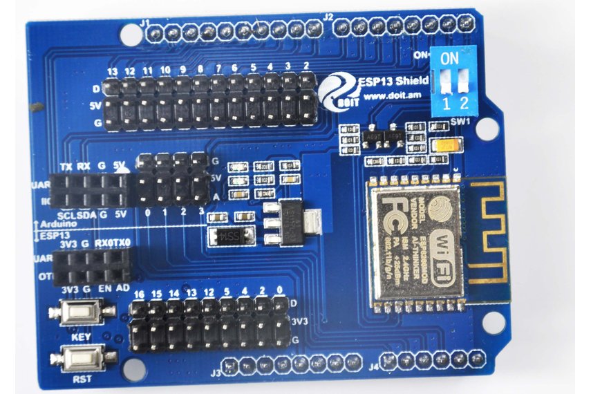
It has the brandname “Duinotech” silk printed on the PCB but appears to be based off a design from the Doctors of Intelligence & Technology (DOIT)
Before we begin make sure your Arduino is flashed with a blank sketch - this will make things much easier.
Fixing the Baud Rate
So, the first problem is the ESP-13 shields UART is set to 115200 baud.
This is way too fast for the Arduino Uno over software serial. So you need to set the baud to 9600.
But unfortunately the pins for serial are swapped. TX goes RX and vice versa, so you need to seperate the shield and wire it up manually.
Note: This is not the same as the serial connection from your PC to the Arduino over USB, which is capable of 115200 baud.
You’ll also need to make sure the dip switches are set to “off” (top right in the above picture)
| ESP-13 | Arduni Uno |
|---|---|
| Debug Port TX (TXO) | Uno Pin 1 (TX) |
| Debug Port RX (RXO) | Uno Pin 0 (RX) |
| Debug Port 5V | Uno 5V |
| Debug Port GND | Uno GND |
Feel free to refer to the picture below for how I wired it.
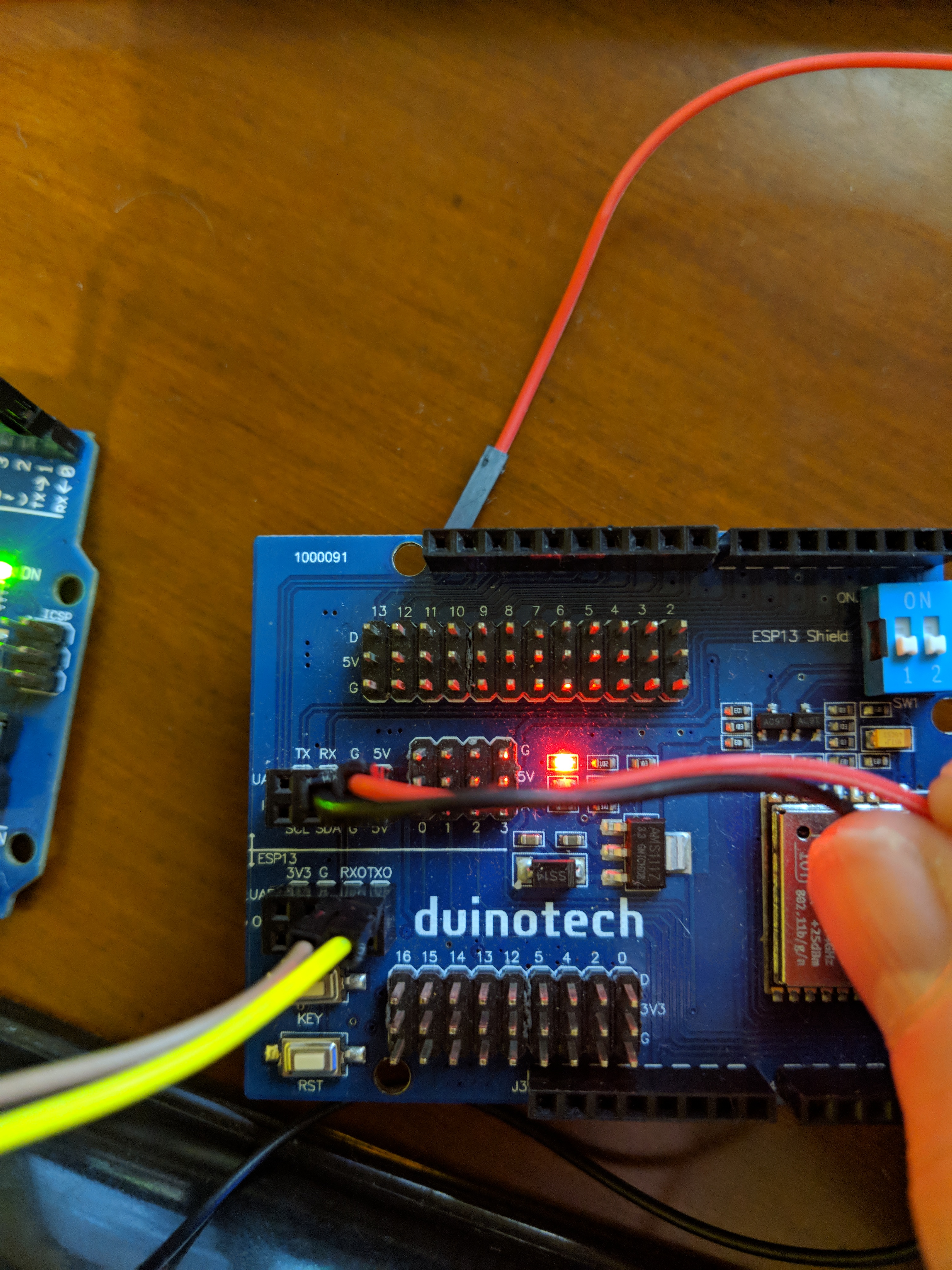
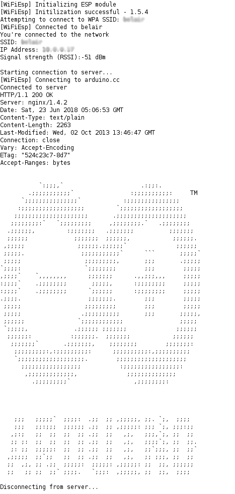
Once you’ve wired it correctly and powered it on you’ll need to look at the serial monitor for the output “ready”. The baud on the serial console should be set to 9600 as well.
You should get some output similiar to below:
�
�F⸮=O⸮a+⸮⸮B&C⸮H⸮!⸮⸮⸮⸮
⸮ea⸮@
�I⸮⸮V
⸮AȈ⸮X⸮Ìܐ⸮V2⸮"�⸮
Ai-Thinker Technology Co. Ltd.
ready
If you see this execute the following AT command to change the baud of the UART serial to 9600
AT+UART_DEF=9600,8,1,0,0
If you recieve an “OK” back you can move to the next step.
Getting it to work
Prerequisites
Once you’ve confirmed the above AT command works, disconnect everything - leaving just the Arduino connected to your PC.
For this step you’ll need the WiFiEsp libary.
If you don’t already have it in the Arduino IDE navigate to “Sketch -> Include Libary -> Manage Libraries” and search for it.
In the Arduino IDE navigate to “Examples -> WiFiEsp -> WebClient”
There are a few variables you need to substitute such as:
SoftwareSerial Serial1(3,2)char ssid[] = "ssid_goes_here"char pass[] = "wifi_pass_here"
Make sure the baud is set to 115200, upload the sketch and confirm it’s successful, then move on.
Connecting to the Server
At this point you should have an Arduino connected to your PC with the WebClient Sketch uploaded. The ESP module should be unplugged at this point. The serial console will complain how the WiFi Shield is not present.
In the sketch we defined new serial ports for the ESP module to communicate on as the Arduino reserves PIN0 and PIN1 for it’s own serial.
So connect jumper wires to match the following:
| ESP-13 | Arduni Uno |
|---|---|
| TX Port | Uno Pin 3 |
| RX Port | Uno Pin 2 |
Note: You should’ve previously used the ones labelled RXO and TXO. You need to use the other TX/RX pins on the ESP, the same section with the 5V pin.
Connect the ground and 5V pin to power the ESP module and flip the DIP switches to “ON”
The wiring for this part should look like the following:
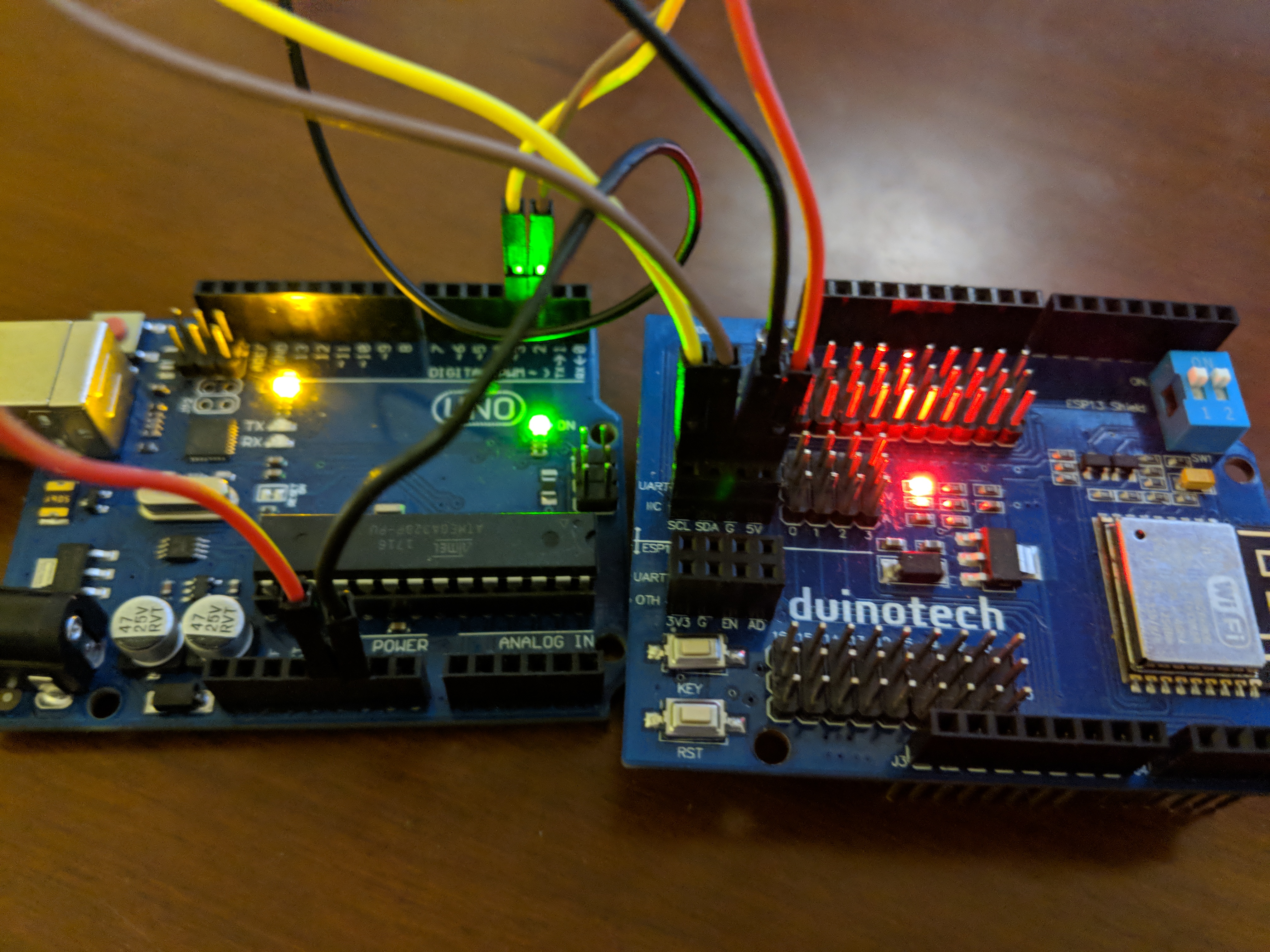
Now press the red reset button on the Arduino, and you should be able to successfully connect to the defined server. Check below for how it should look:
Troubleshooting
A few people have commented and are running into some problems talking to the ESP module to send the required AT commands, here’s a few things to try.
Power
Firstly, make sure the power lights are on the module - there should be a solid red light next to the 5v LED on the board. Don’t proceed if at least this part is working. You can power the board a number of ways, there’s 5V pins on the left side of the board (the UART) headers, or you can match the pins on the outside with the ones on the arduino. I’d recommend the UART header as it’s clearer, refer to the pictures if you’re not sure.
Wiring
It’s not necessary to use a breadboard for this, but you can if you want.
The arduino provides power to the module and needs to connect to it (either directly, or via a breadboard). On the Arduino the power is provided by the 5v pin, which should be clearly marked.
The data tx/rx wiring is a bit more trickier, but make sure you are connecting the RXO/TXO on the board ESP module when you are running AT commands (NOT RX and TX). This means one section of the UART just has power (5v and GND) and the other section has RXO and TXO. They need to match on both sides, i.e TX -> TXO and RX -> RXO. When you are finished with the AT commands you need to connect to TX/RX on the ESP.
If you have the serial monitor open and are changing the wires over and want refresh the monitor just pull the red wire from the ESP module and plug it back in again.
DIP Switch
This should be OFF when you are running AT commands, and ON when you are using it as a shield.
Good luck